Post
How I Automated My Water Tank Supply
A story involving laziness that ended with me climbing up a ladder to install a sensor to control my water tank supply.
So over the past few years I have become obsessed with Home Automation. The journey started off with just automating a few light bulbs outside my house using Google Home and some cheap smart switches from Amazon, all because I was too lazy to keep switching them on when it got dark. From that it’s now evolved into a proper Linux server powered by Home Assistant, with 100+ smart devices, 50+ automations, and monitoring for all kinds of sensors, from energy usage, to solar generation, air quality, network reliability, media management and what not. I may cover some of the other stuff later on. But I specifically wanted to talk about a custom solution I built for my water tank supply which I was especially proud of. So this is me showing off.
 Photo by Jainath Ponnala on Unsplash
The background#
My home relies on a backyard well for our daily water supply. However, to actually get that water into the house, we have to run pumps to fill an overhead tank on the roof. So in essence, while we technically have an “unlimited” water supply, someone has to manually turn on the pump, wait about 20 minutes for the tank to fill, and switch it off whenever it starts overflowing. The main problem was that you were never really sure how much water was in the tank at any given moment.
The idea#
It was clear to me that this was a routine task ripe for automation. The goal was simple: continuously measure the water level in the tank, automatically turn on the water pump via smart switches when the level dropped low enough, and switch it off once full (defined either by reaching a target fill level or right before overflowing). So I got to work designing the setup and sourcing the parts I’d need.
The problem#
The biggest hurdle to tackle in this entire project would be figuring out how to reliably measure the water level in the tank. There were a bunch of different methods, of course, which I will list below:
-
A float switch (or reed switch array), which is a floating device (or vertical tube with magnetic reed switches inside) suspended in the tank. As the water level rises or falls, a buoyant magnet moves along the tube and closes reed switches positioned at different fixed heights (such as 25%, 50%, 75%, or 100%), sending a signal whenever the water reaches those specific levels. So this serves as a cheap way to measure water level, though the main problem here is there is no continuous realtime measurement, it only tells you in discrete measurements.
-
An ultrasonic sensor, which is placed under the lid of the water tank to fire ultrasonic waves at the water surface. Using time-of-flight math, it estimates the distance to the water based on how long the sound takes to reflect back. Low cost as well, but if the water surface is agitated (which is always the case when the pump is pouring in water), the measurements can go haywire and we have no idea what the true water level might be.
-
A submersible pressure sensor, which is a higher-cost but extremely reliable option. It is fully waterproof and sits at the very bottom of the tank. Powered continuously, it outputs an analog signal based on the hydrostatic water pressure above it, which can be converted into exact, continuous water depth readings.
As I had the money to spare and I wanted to make sure the sensors worked for years when I wouldn’t be home, I opted for option 3.
The materials#
Now before I could start building anything, I needed to figure out how to actually power and connect the device. The water tank sits on the terrace of my house, where there are no power plugs available and WiFi connectivity is spotty at best, not to mention it gets even worse during the rains. So running a WiFi-based solution with a separate power source wasn’t going to cut it.
That’s when the idea of PoE (Power over Ethernet) hit me like a light bulb. A single ethernet cable could carry both data and power up to the terrace. No need for a power outlet up there, no worrying about WiFi dropping out mid-automation. Problem solved.
With that figured out, here’s the full list of parts I ended up using:
| # | Part | Cost (₹) | Notes |
|---|---|---|---|
| 1 | Gravity: Submersible Pressure Level Sensor (0~5m) + Current to Voltage Converter | ₹4,438 | Bought as a combo on sale from DFRobot. The sensor goes in the tank, the converter translates its 4-20mA signal to voltage for the Arduino. |
| 2 | Arduino Uno R3 | ₹1,748 | Already owned, bought about 10 years ago. |
| 3 | Ethernet W5100 Shield | ₹584 | On sale. Sits on top of the Arduino for wired ethernet. |
| 4 | 15m Weatherproof Ethernet Cable | ₹419 | Outdoor rated, runs from downstairs to the terrace. |
| 5 | 24V 2.5A Power Adapter | ₹499 | Powers the whole setup via the PoE injector. |
| 6 | Passive PoE Injector and Splitter pair | ₹229 | Injector downstairs combines power + data, splitter on the terrace separates them. |
| 7 | DC-DC Buck Converter 6V-24V to 5V 3A USB Output Module | ₹219 | Already owned. Steps down voltage to 5V with a USB output for the Arduino. |
| 8 | USB-A to USB-B cable | ~₹100 | Already owned. Connects the buck converter to the Arduino. |
| 9 | Waterproof Sealed Electrical Outdoor Box | ~₹200 | Bought locally. Houses all the electronics on the terrace. |
| 10 | BMP280 Temperature and Pressure Sensor | ₹250 | Monitors conditions inside the sealed box. |
| Total | ~₹8,686 |
Yeah, it’s not cheap. As I mentioned earlier, I knew the submersible pressure sensor route was going to be the expensive option, and this table pretty much confirms it: the sensor alone accounts for over half the total cost. But this was a personal project and cost was not a factor for me; I wanted reliability and accuracy above all else. If the cost-to-benefit ratio doesn’t seem worth it to you, I’d definitely recommend looking into the float switch or ultrasonic sensor options I mentioned earlier. They’re significantly cheaper and can absolutely get the job done for most use cases.
Funny story about the BMP280: I actually wanted a BME280 sensor which can measure humidity, so I could monitor whether the box was truly airtight. But I got duped into buying a BMP280 instead, which doesn’t do humidity. Classic. It still works for temperature and barometric pressure though, so at the very least I can keep an eye on whether the box is getting too hot up there in the sun.
The wiring#
Alright so let’s talk about how everything is actually connected.
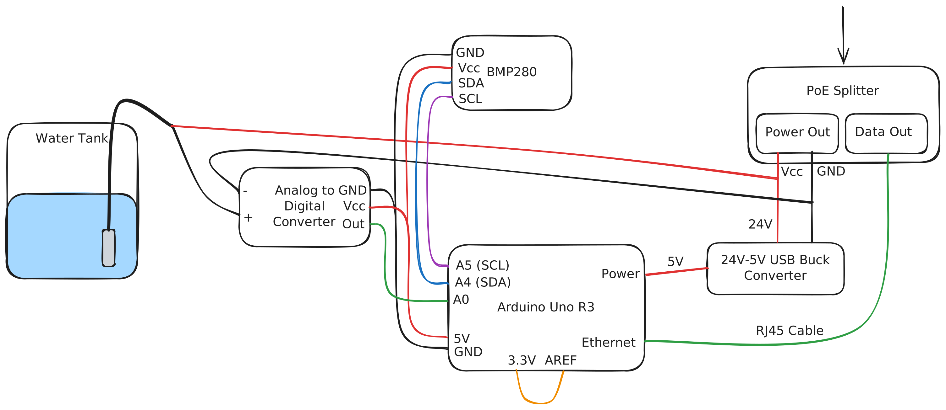 The pinout configuration for the water tank sensor.
Starting from downstairs, the PoE injector sits near my router and the 24V power adapter. It combines the ethernet connection and power into a single cable (the 15m weatherproof ethernet cable) which I ran all the way up to the terrace.
Now the water tank itself sits on top of a large metal platform, and conveniently the underside of this platform is hollow, which provides a nice sheltered spot protected from rain. This is where I placed the sealed electrical box with all the equipment inside.
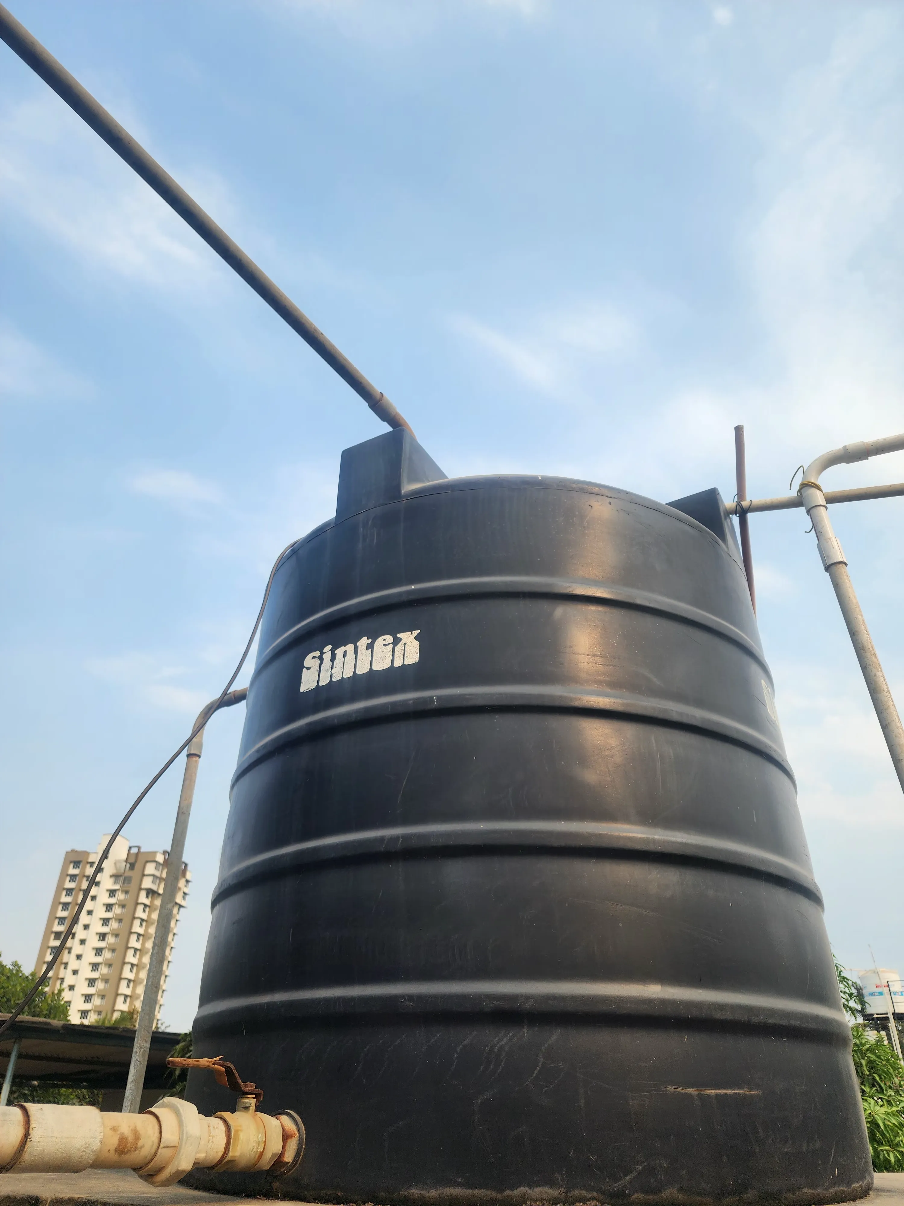 The water tank positioned on the elevated metal platform on the terrace.
Inside the box, the PoE splitter takes the incoming ethernet cable and separates it back into two things: ethernet data and power. The ethernet goes straight into the W5100 Ethernet Shield which sits on top of the Arduino Uno. For the power side, the 24V line splits off in two directions: one goes to the DC-DC buck converter which steps it down to 5V to power the Arduino via USB, and the other goes to power the water pressure sensor.
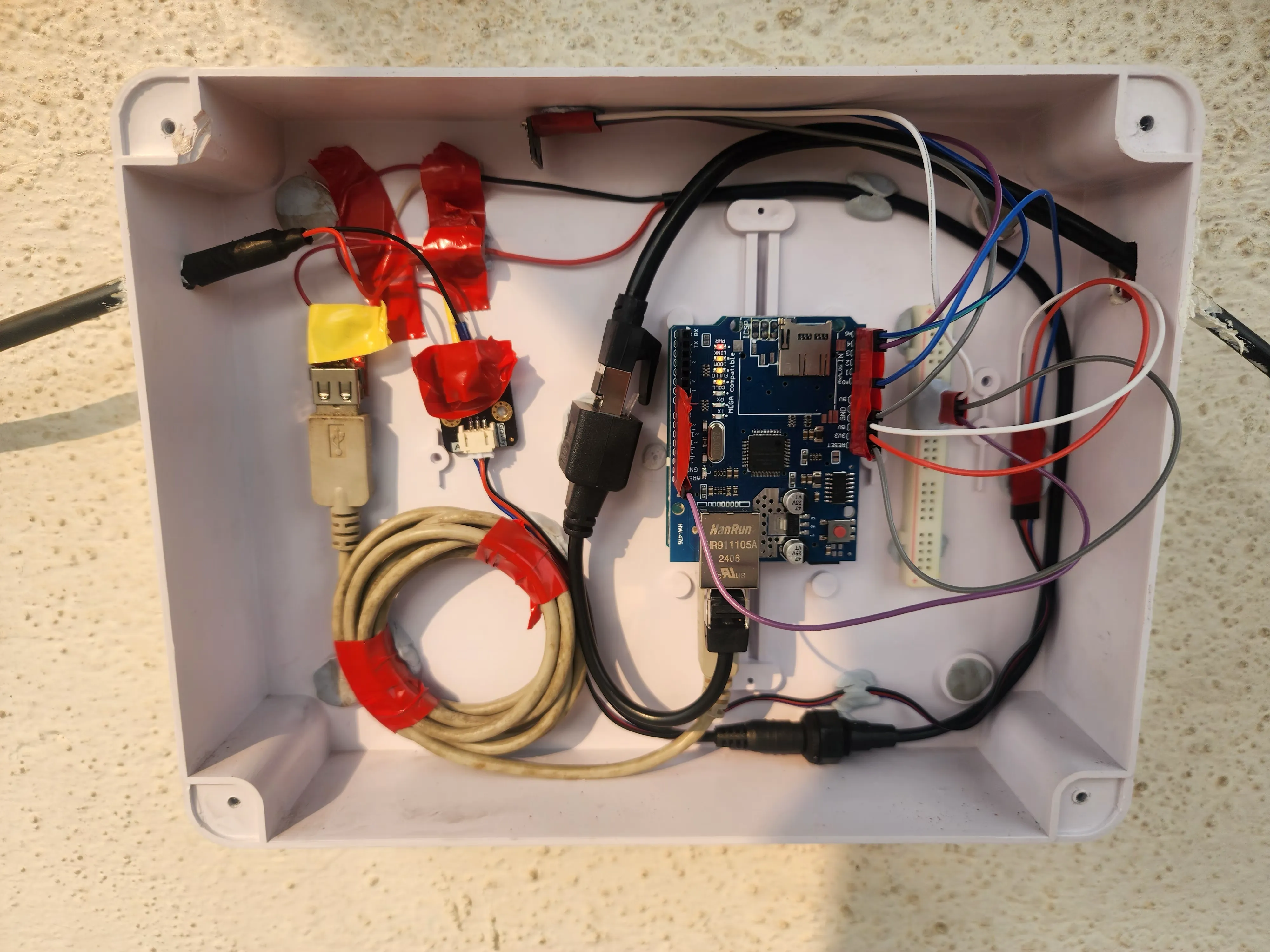 The internal layout of the sealed electrical box showing the Arduino, PoE splitter, and buck converter.
For the sensor itself, the power and ground wires come into the box, while the actual sensor cable runs up and out of the box into the water tank above. Now here’s the part where the blog description comes full circle: to get the sensor inside the tank, I had to climb up a ladder onto the metal platform, remove the heavy tank lid, drill a hole through it for the cable, feed the sensor in, and seal it all back up. Not exactly the most glamorous part of a home automation project, but someone had to do it. The sensor works as a closed current loop: power flows through it, and the return path via the ground (black) cable is routed through a current-to-voltage converter board. The converter monitors the current flowing through the loop, which changes based on water pressure, and converts it into an analog voltage signal that gets passed to the Arduino via one of its analog pins.
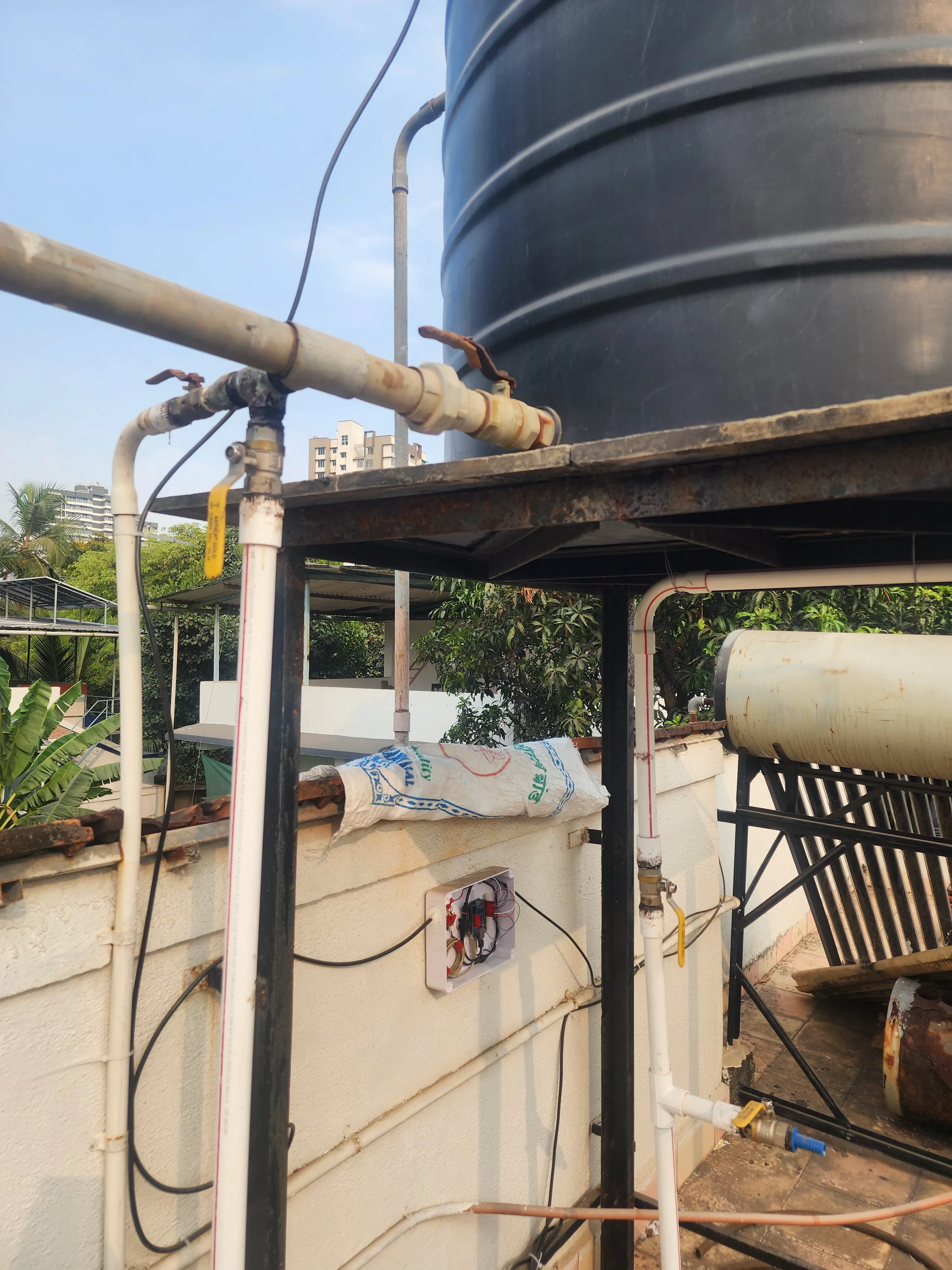 The pressure sensor cable routed into the top of the water tank.
The BMP280 temperature and pressure sensor connects to the Arduino via the SDA and SCL ports (I2C), tucked inside the box to keep an eye on the internal conditions. And one important detail: I connected the AREF pin on the Arduino to the 3.3V output. This sets the analog reference voltage, which becomes important in the code logic we’ll get into next.
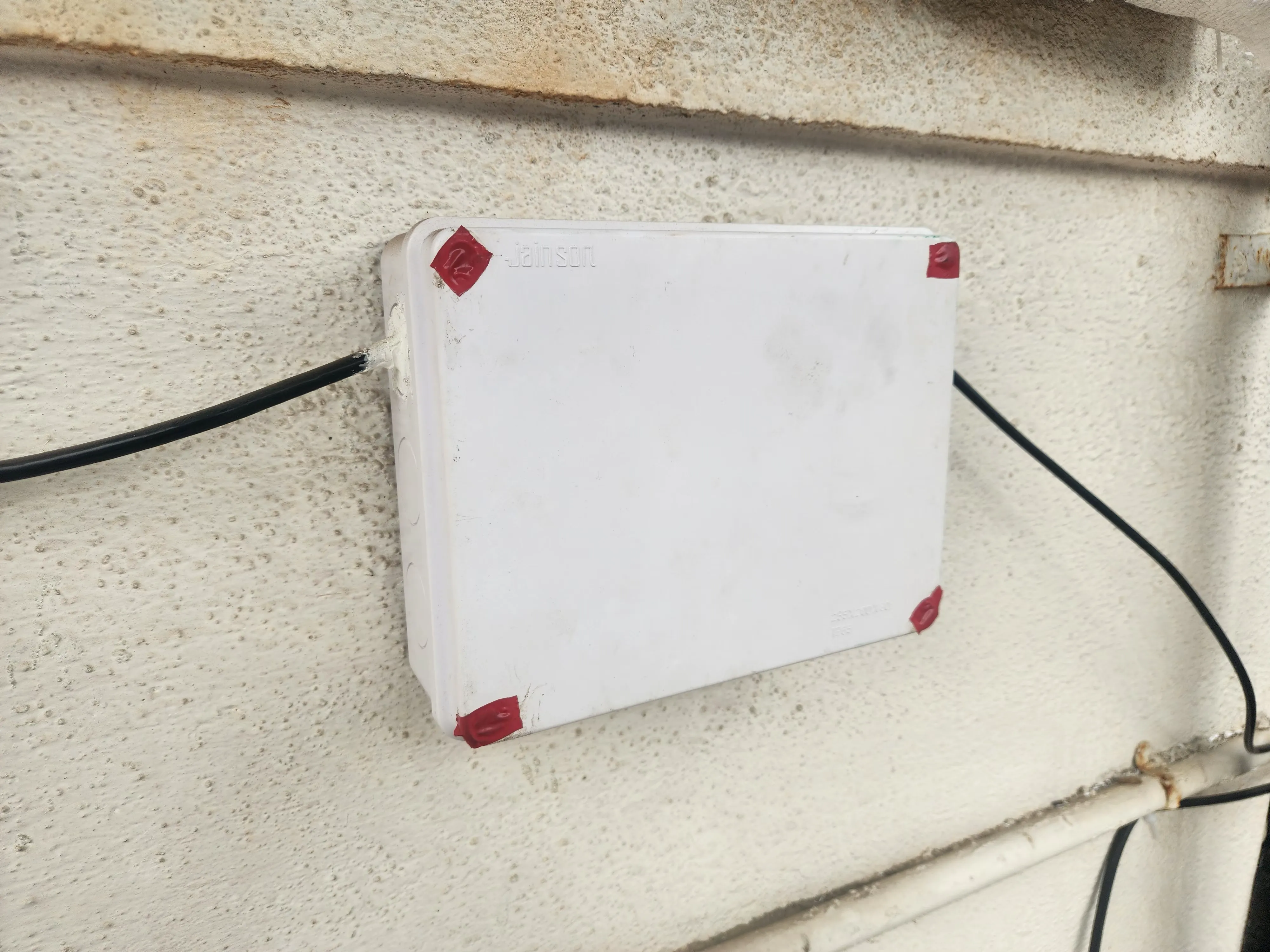 The fully assembled and sealed waterproof box mounted securely under the platform.
The code#
With the hardware all wired up, it was time to write the software. The main job of the Arduino is fairly straightforward: read the analog water level sensor, read the BMP280 sensor for temperature and pressure, and publish all of that to my Home Assistant server. The best way to do that over a wired ethernet connection is MQTT. A prerequisite for this of course was having an MQTT broker already running: I had Mosquitto set up on my home server as part of my existing Home Assistant setup, so that was already taken care of.
For the water level calculation itself, DFRobot provides sample code on their wiki that I used as the starting point. The core logic reads the analog voltage from the current-to-voltage converter board, derives the current flowing through the sensor’s 4-20mA loop via a 120 ohm sense resistor, and then calculates the water depth from that current value. I adapted this for my setup and added everything else on top.
Now here’s where things got interesting: the Arduino Uno has very limited memory. I’m talking 32KB of flash and 2KB of SRAM. I was not used to working within such tight constraints and it was honestly quite the learning experience trying to optimize things. I couldn’t just throw in any library I wanted. For instance, I would have loved to implement MQTT auto-discovery so Home Assistant would automatically detect the sensors, but the JSON payloads alone would have blown through the memory budget. So instead I went with manually configuring the MQTT sensors on the Home Assistant side and kept the Arduino code as lean as possible.
The libraries I ended up using were carefully picked for their small footprint:
- Ethernet - for the W5100 shield, handles the wired network connection.
- PubSubClient - a lightweight MQTT client. Does exactly what it needs to and nothing more.
- MedianFilterLib - this one was key for dealing with noisy sensor readings (more on that below).
- Wire - the standard I2C library for communicating with the BMP280.
- forcedBMX280 - a super minimal BMP280 library that uses forced measurement mode. Way smaller than the Adafruit alternative.
A lot of the memory optimizations in the code actually came from my debugging sessions with Claude. For example, instead of using
sprintfwith%fto format floating point numbers (which on AVR pulls in a massive floating-point printf library and eats up flash), I useddtostrfwhich does the same job at a fraction of the cost. And rather than allocating separate buffers for each sensor value, a single sharedchar buf[16]is reused across all thedtostrfandmqtt.publishcalls. I also used theF()macro on all the serial print strings, which stores them in flash (PROGMEM) instead of eating into the precious 2KB of SRAM. These are tiny things individually but on the Uno they were the difference between the sketch fitting or not.
One challenge I ran into early on was that the analog sensor readings were constantly fluctuating and had occasional spikes, likely from voltage noise given the analog nature of the signal. I had already done a few things on the hardware side to help with this: reading from the ground side of the sensor instead of the voltage side, using the same 24V supply stepped down for both the sensor and Arduino to keep things clean, and connecting AREF to 3.3V. That last part is important: by using analogReference(EXTERNAL) in the code and setting VREF to 3300mV, the Arduino’s ADC maps the full 0-1023 range across 0-3.3V instead of 0-5V. Since the sensor’s signal falls well within this range, we get better resolution and less noise in the readings.
But even with all of that, the readings still jumped around enough to be problematic. So I added a median filter. The MedianFilterLib takes 100 consecutive readings and returns the median value, which effectively filters out those random spikes. It’s a simple but very effective approach for this kind of noisy analog data.
The code publishes updates every 10 seconds via MQTT, though honestly it could send readings every millisecond if needed. That’s the beauty of analog sensors! Every update includes the filtered water depth, raw voltage and current readings (useful for debugging), and the BMP280’s temperature and pressure. There’s also an availability topic so Home Assistant knows whether the device is online or offline.
Here’s the full sketch:
#include <Ethernet.h>
#include <PubSubClient.h>
#include <MedianFilterLib.h>
#include <Wire.h>
#include <forcedBMX280.h>

#define BROKER_ADDR IPAddress(192, 168, x, x)
#define MQTT_PORT 1883
#define MQTT_USERNAME "your_mqtt_username"
#define MQTT_PASSWORD "your_mqtt_password"
#define UPDATE_INTERVAL 10000
#define ANALOG_PIN A0
#define RANGE 5000         // Depth measuring range 5000mm (for water)
#define VREF 3300          // ADC's reference voltage on your Arduino,typical value:5000mV
#define CURRENT_INIT 4.00  // Current @ 0mm (uint: mA)
#define DENSITY_WATER 1    // Pure water density normalized to 1
#define MEDIAN_PERIOD 100

byte mac[] = { 0xDE, 0xAD, 0xBE, 0xEF, 0xFE, 0xED };

EthernetClient ethClient;
PubSubClient mqtt(ethClient);

int16_t dataVoltage;
float dataCurrent, depth;  //unit:mA
unsigned long lastUpdateAt;

MedianFilter<uint16_t> medianFilter(MEDIAN_PERIOD);

ForcedBMP280Float climateSensor = ForcedBMP280Float();

const char* levelTopic = "waterlevel2mqtt/waterLevel";
const char* currentTopic = "waterlevel2mqtt/dataCurrent";
const char* voltageTopic = "waterlevel2mqtt/dataVoltage";
const char* tempTopic = "waterlevel2mqtt/temperature";
const char* pressureTopic = "waterlevel2mqtt/pressure";
const char* availabilityTopic = "waterlevel2mqtt/availability";

void setup() {
  Serial.begin(9600);
  Ethernet.begin(mac);
  Wire.begin();
  delay(1500);  // Give Ethernet some time

  analogReference(EXTERNAL);
  pinMode(ANALOG_PIN, INPUT);

  climateSensor.begin();
  delay(1000);

  mqtt.setServer(BROKER_ADDR, MQTT_PORT);

  lastUpdateAt = millis();

  Serial.println("Started");
}

void reconnect() {
  while (!mqtt.connected()) {
    Serial.println(F("Connecting to MQTT..."));
    if (mqtt.connect("waterlevel2mqtt", MQTT_USERNAME, MQTT_PASSWORD, availabilityTopic, 0, true, "offline")) {
      Serial.println(F("Connected!"));
      mqtt.publish(availabilityTopic, "online", false);
    } else {
      Serial.print(F("Failed, rc="));
      Serial.print(mqtt.state());
      Serial.println(F(" retrying in 5s"));
      delay(5000);
    }
  }
}

void readData() {
  dataVoltage = (analogRead(ANALOG_PIN) / 1023.0) * VREF;
  dataCurrent = dataVoltage / 120.0;                                        //Sense Resistor:120ohm
  depth = (dataCurrent - CURRENT_INIT) * ((RANGE / DENSITY_WATER) / 16.0);  //Calculate depth from current readings
  if (depth < 0) depth = 0.0;
}

void loop() {
  Ethernet.maintain();
  if (!mqtt.connected()) {
    reconnect();
  }
  mqtt.loop();

  readData();

  Serial.print("Water Depth: ");
  Serial.print(depth);
  Serial.println("mm");

  medianFilter.AddValue((uint16_t)depth);

  if ((millis() - lastUpdateAt) > UPDATE_INTERVAL) {
    lastUpdateAt = millis();
    climateSensor.takeForcedMeasurement();

    mqtt.publish(availabilityTopic, "online", false);

    char buf[16];

    dtostrf(medianFilter.GetFiltered(), 1, 0, buf);
    mqtt.publish(levelTopic, buf, false);

    dtostrf(dataVoltage, 1, 0, buf);
    mqtt.publish(voltageTopic, buf, false);

    dtostrf(dataCurrent, 1, 3, buf);
    mqtt.publish(currentTopic, buf, false);

    dtostrf(climateSensor.getTemperatureCelsiusAsFloat(), 1, 2, buf);
    mqtt.publish(tempTopic, buf, false);

    dtostrf(climateSensor.getPressureAsFloat(), 1, 2, buf);
    mqtt.publish(pressureTopic, buf, false);
  }
}
The automation setup#
With the Arduino powered on and sensor data flowing in via MQTT, the next step was getting Home Assistant to actually make sense of it all. For pump control, I had installed Shelly Plus 1 Mini Gen3 PM smart switches on the water pump switches. Shelly integrates natively with Home Assistant, so controlling the pumps was as simple as toggling a switch entity.
Now since the Arduino code doesn’t support MQTT auto-discovery (thanks to memory constraints), I had to manually define all the sensors on the Home Assistant side using the MQTT integration. Each sensor subscribes to its respective MQTT topic and is grouped under a single device called WaterTankLevel2MQTT. Here’s a summary of the sensors I configured:
| Sensor | MQTT Topic | Unit | Purpose |
|---|---|---|---|
| Water Tank Level | waterlevel2mqtt/waterLevel | mm | The main water depth reading from the pressure sensor |
| Data Current | waterlevel2mqtt/dataCurrent | mA | Raw current from the 4-20mA loop, useful for diagnostics |
| Input Voltage | waterlevel2mqtt/dataVoltage | mV | Raw voltage from the current to voltage converter, for diagnostics |
| Device Temperature | waterlevel2mqtt/temperature | °C | BMP280 temperature inside the enclosure |
| Device Pressure | waterlevel2mqtt/pressure | hPa | BMP280 atmospheric pressure inside the enclosure |
All sensors share the same waterlevel2mqtt/availability topic so Home Assistant knows if the device goes offline.
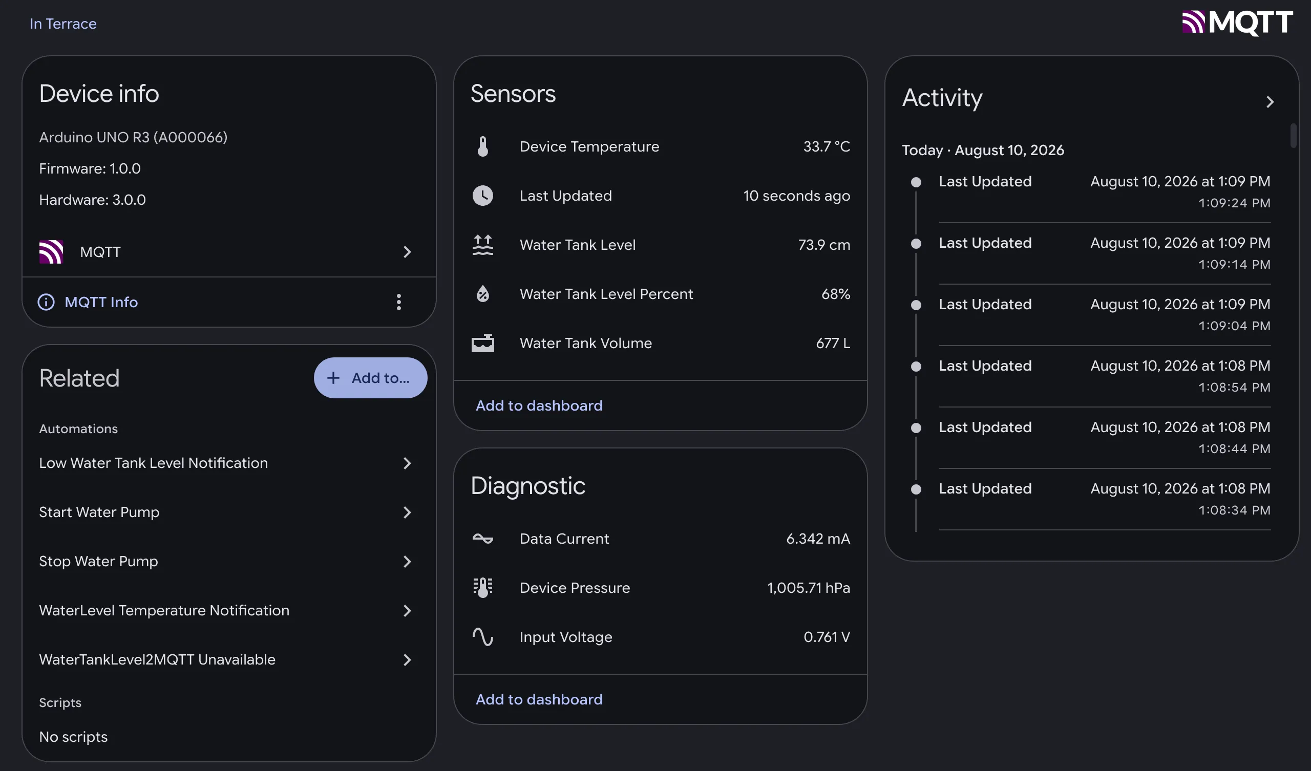 The manually configured MQTT sensors for the water tank appearing in Home Assistant.
But the raw depth reading in millimeters alone wasn’t particularly useful on its own. What I really wanted to know was how much water was in the tank in litres and as a percentage. So with some good old fashioned math and geometry (knowing the tank’s dimensions and shape) I created template sensors in Home Assistant that convert the depth reading into an estimated volume in litres. I then measured the sensor reading when the tank was completely full, marked that as the 100% level, and was able to calculate a percentage from there. Now I could see at a glance that the tank was at, say, 72%, making it way more intuitive than “depth: 843mm”.
With all the sensor data and percentage calculations in place, I was finally able to create the automations that were the whole point of this project. The logic is simple: when the water level drops below 40%, turn on the water pump via the Shelly switch. When it reaches 100%, turn it off. Set it and forget it.
But I didn’t stop there. Since the sensor is continuously measuring water depth, I realized I could also calculate water consumption over time. Using some math to track the rate of decrease in water level, I was able to register the water usage of my house via Home Assistant’s Energy dashboard. This gives me some interesting insights for the future, or at the very least helps me find out if someone left the flush running or if there’s a leak somewhere.
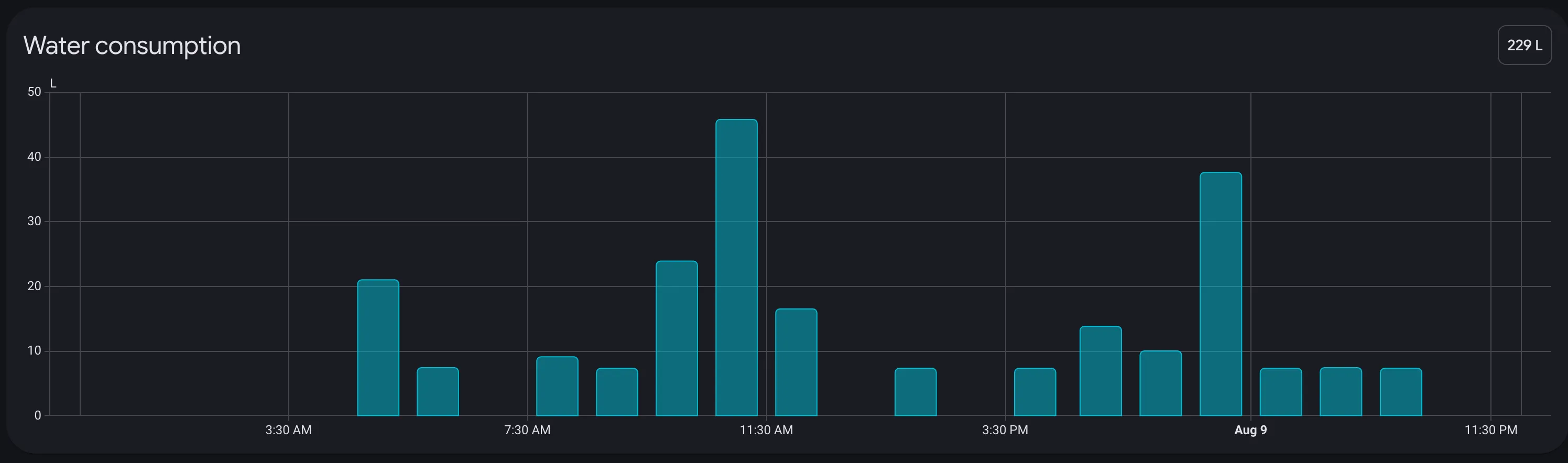 Tracking overall water consumption via the Home Assistant Energy dashboard.
I also set up a bunch of alerts: notifications if the water level gets critically low, and (this one actually saved me) an alert if the pumps are running but the water level isn’t increasing, which would indicate a pump failure. That exact scenario happened a few months back and the alert caught it immediately.
And this is really the power of home automation when you think about it. I literally added just one sensor (a water depth sensor) and from that single data point I was able to extrapolate water volume, tank percentage, automated pump control, water usage tracking, and failure detection. All from one sensor and some creative thinking.
The results#
It’s been about 10 months with this setup in place now, and it has been working flawlessly. No more manually switching on the pump and waiting around for the tank to fill up: there’s complete peace of mind knowing the water level is managed automatically. Having exact visibility into how much water is left is also great information to have, especially for catching potential pump issues before they turn into major problems.
My parents are definitely happy with the setup now, even if they were thoroughly confused about what I was up to with ladders and cables at first!
This was easily one of the most fun and rewarding projects in my home automation journey, and I hope you learned something from it or got inspired to build something similar for your own home. I’m completely hooked on home automation at this point, so I’ll definitely be writing more posts about other parts of my setup down the line.
Thanks for reading!